|
SUPPORT SITE |
|
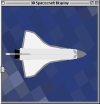
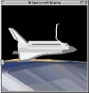
The CAD tools allow very elaborate visualization. The figures to the right show a simulation of the Space Shuttle Orbiter with the Remote Manipulator being deployed. You can build models, which can include multiple components as shown here, and animate each component. Besides animation, you can simulate multi-body models, compute disturbances for those models and connect controllers to the models.


Stellar attitude determination employs star trackers and gyros to provide precise attitude information. The gyros provide rate information which is integrated to get the inertial attitude. The star trackers provide corrections to adjust for gyro noise. The model used in the Kalman Filter is a noise dynamics model of the gyros. The toolbox estimation module includes functions for attitude determination with the star tracker alone, for the case where there are no gyros or the gyros are off-line. Key features are
The stellar attitude determination system has two modes of operation. The first is acquisition mode when the attitude uncertainty is large. The second is tracking mode when the uncertainty is small. The former mode uses intensity and pattern matching to identify stars which can then be tracked to provide bias corrections for the gyros. The system automatically switches modes as needed.


Orbit determination is performed using nonlinear recursive orbit estimation employing a continuous discrete extended iterated Kalman Filter (CDEIKF); the state includes 3 states per axis for unmodeled disturbances. The filter uses average properties of the spacecraft for disturbance calculations. The gravity model may contain any number of zonal and tesseral gravity harmonics. Any gravity model can be used. Best performance will be obtained if the harmonic coefficients are derived from data for a similar orbit.

The propagator interface is to the right. The user can select force models, initial conditions, gravity models and stopping conditions through the GUI. In addition, the user can create his or her own control routines for feedback orbit control. All of the force models use m-files that can be customized by the user. Force models from the Spacecraft Control Toolbox can be used for high-fidelity solar pressure and drag calculations.


Many spacecraft use blowdown propellant pressurization systems. The fuel is loaded into the tanks and then it is pressurized using helium. The volume of pressurized helium, the mass of the fuel and the total system volume determines the pressure when the tank is fuel and the pressure when it is empty. This defines the blowdown curve. The total volume must be selected so that the minimum pressure is acceptable. If it is too low the thrusters will not function. Typical blowdown curves start at 350 psi and end at 100 psi.

The graph to the right shows vehicle mass properties, etc. as a function of exhaust velocities with constant thrust. You can clearly see that there is an optimal exhaust velocity which comes about because the power plant mass increases with increasing exhaust velocity but the fuel mass (and tankage) decreases.

In 1948 Claude E. Shannon published a paper showing that the information content of a communication channel is determined by both its bandwidth and by its output signal-to-noise ratio. The information content is the product of the bandwidth and the base 2 log of 1 + the power signal-to-noise ratio. The plot, generated by the Shannon.m function in the Link module, on the right shows the information capacity divided by the bandwidth as a function of signal-to-noise ratio. Shannon's formula is used for communications, radar and vision systems.

The plot to the right shows link margins as a function of orbital position.

This plot is generated by the WiensDsp.m function in Thermal. It shows the peak block body frequency as a function of black body temperature.

Sun nadir pointing control is used on numerous spacecraft, such as GPS II and Topex. In a sun nadir design the spacecraft is steered around yaw and the solar arrays steered about pitch so that the arrays are always normal to the sun. This maximizes the power output from the solar arrays and eliminates the need for an additional hinge. When the sun angle is low with respect to the orbit plane, the spacecraft flips 180 deg at noon and midnight
This design uses a four reaction wheel pyramid for control. Magnetic torquers are used for momentum unloading. Analog sun sensors on the solar array tips are used to generate the yaw attitude measurement. Since the arrays normal points at the sun this measurement is available for most of the orbit, unlike that from a body mounted sun sensor. An earth sensor measures roll and pitch.
The plots on the right show the analog sun sensor eyes, which are mounted on the solar arrays and the sun nadir trajectory, Momentum control by the magnetic torquers is shown in a figure shown above.


This approach is similar to the one used for the Microwave Anisotropy Probe. The spacecraft needs to rotate such that one of its axes is offset from a fixed inertial direction. This can be done with reaction wheels. The plot shows the precession angle history.

A low-cost approach to geosynchronous spacecraft control system design is to use a fixed momentum wheel for pitch control, magnetic torquers for roll yaw control, and monopropellant thrusters for 3-axis control during stationkeeping. The spacecraft is spin stabilized during transfer orbit and orbit insertion is done using a solid rocket. The spacecraft transitions from spinning to momentum bias using the dual-spin turn shown below. The algorithms provided in these functions are the same that were used by Princeton Satellite Systems to develop the Indostar/Cakrawarta-1 satellite attitude control system. That satellite has been flying since 1997! The plot on the right shows the pitch loop performance.


The minimum pulsewidth of thrusters presents a major challenge to designers of thruster control systems. Usually the minimum pulsewidth is around 20 msec and for small spacecraft that is a significant torque impulse. The plot to the right shows different methods of dealing with the resolution problem. The ideal case is shown as is the case where there is not compensation for minimum pulsewidth. The two methods that work reasonably well are applying triangle wave dither, which should ideally eliminate the nonlinearity, and applying a variable pulsing period. In the latter you don�t fire your thrusters every control period. Rather you undersample and fire once every few control samples. This works well but you must be careful to account for the new, longer, zero-order hold in your design!
